


Project Date:
June 25, 2016
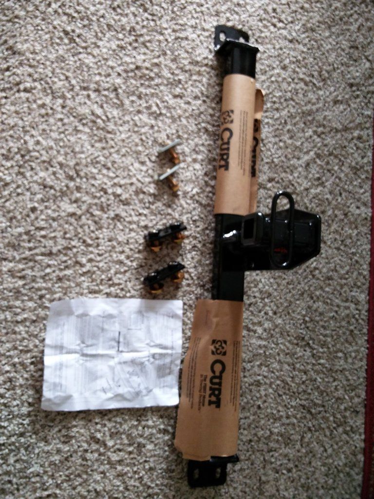
The trailer hitch I purchased is a Curt Manufacturing C11192 which is a class 1 (2000 lbs trailer, 200 lb tongue weight).
https://www.etrailer.com/Trailer-Hitch/Audi/A3/2013/C11192.html?vehicleid=20139158
Installation instructions are here: http://www.etrailer.com/instructions.aspx?pn=C11192
but the detail is a bit scarce when it comes to the tailight and bumper removal so I took my own pictures.
The trailer hitch is of very high quality. I had planned on replacing the hardware with grade 8 stainless (had some rust issues in the past with other cars) but the hardware provided was already grade 8 zinc plated.
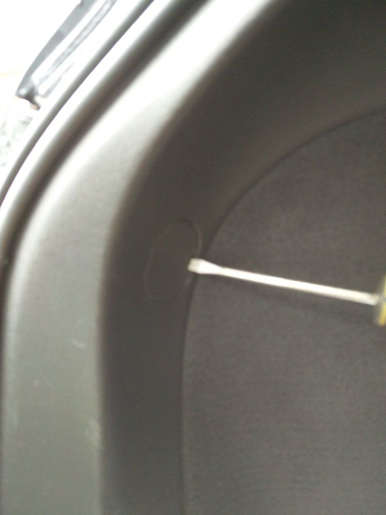
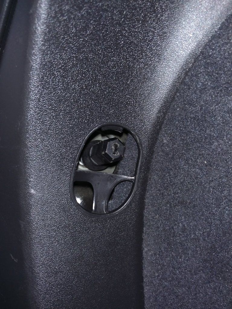
First step, remove the tailights. Inside the trunk, there are two pop out covers that hide the 13mm nut holding the tailights in.
Once the nut is off, rotate the light away from the car. There are two little snap thingies that hold the front part of the light to the body. You should be able to get it free just with your fingers but you can pry (careful with the paint!) if needed.
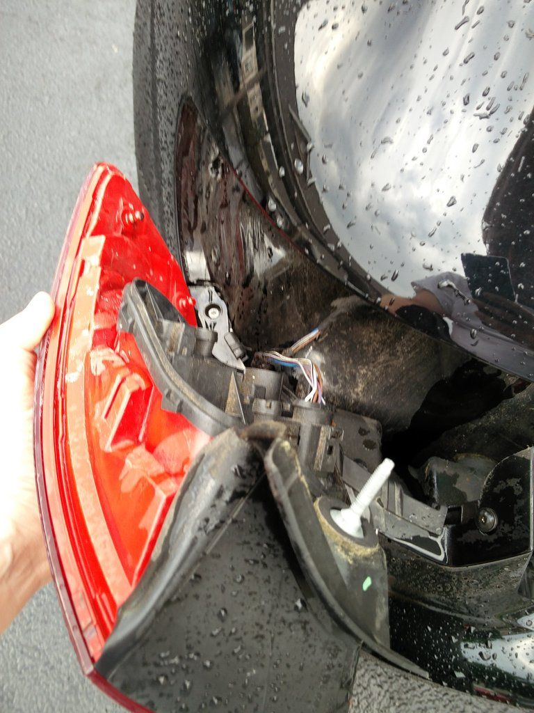
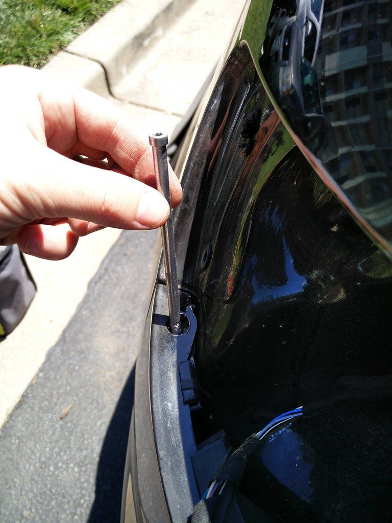
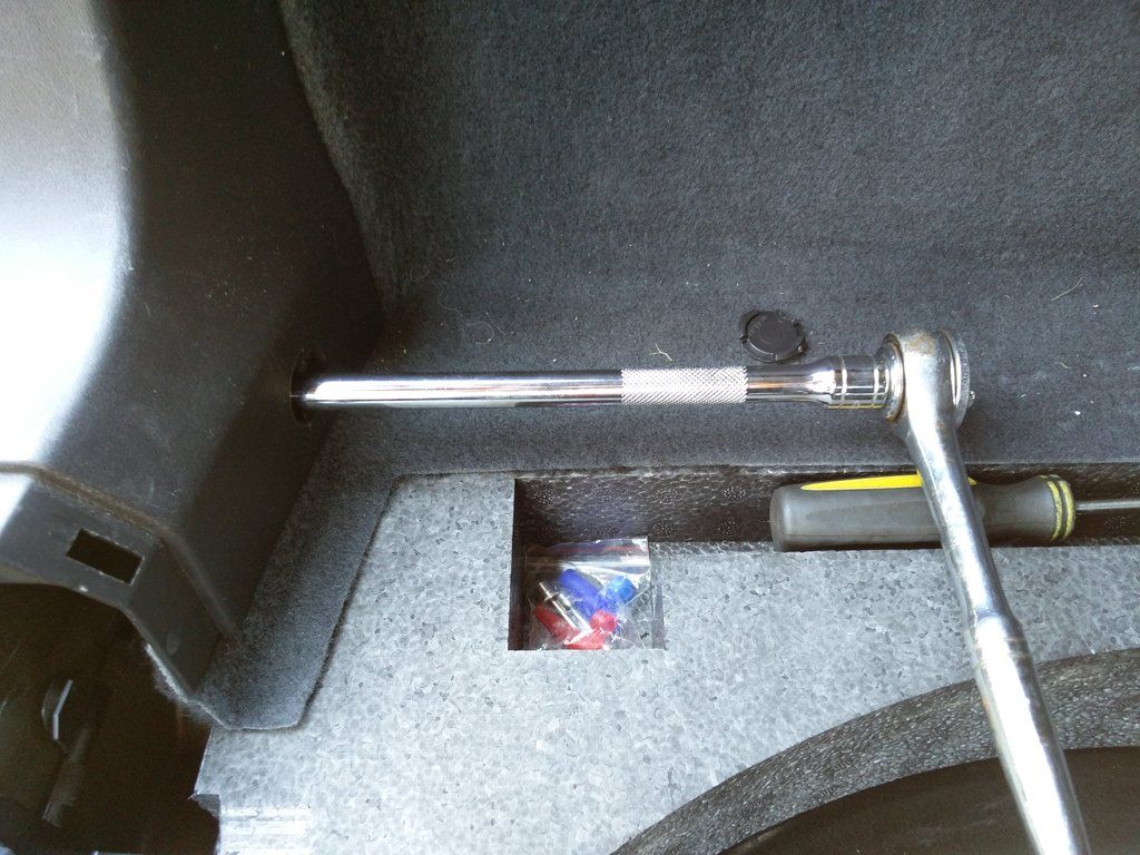
Next, remove the two torx bolts under each tailight.
(Note the silver one is very long)
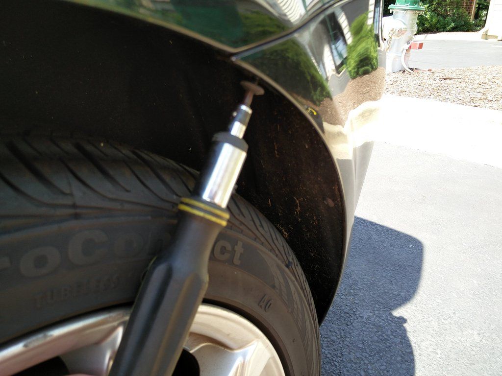
and the three torx bolts inside each wheel well (hint, a right angle torx bit really helps!)
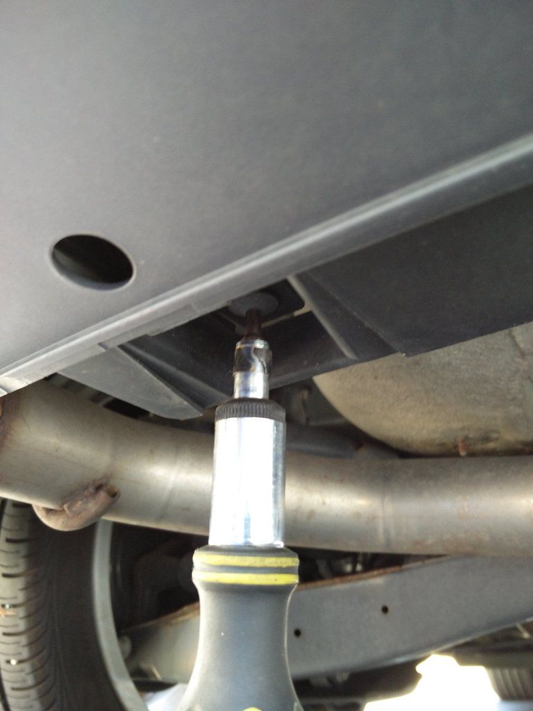
and the two torx bolts underneath the bumper.
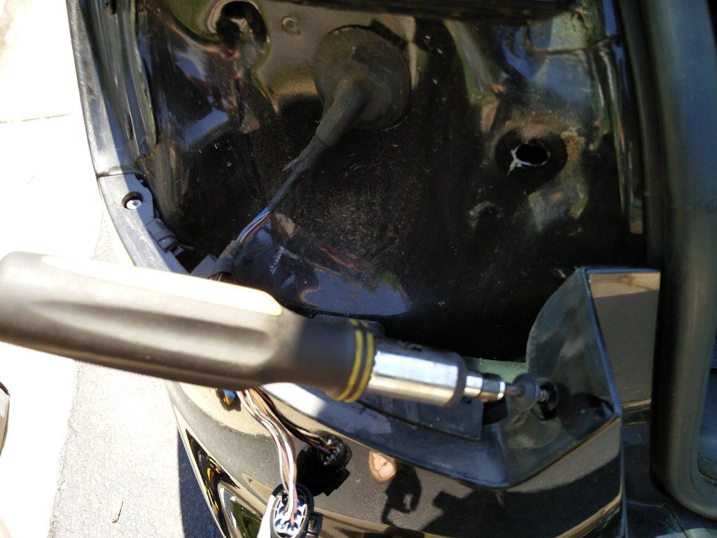
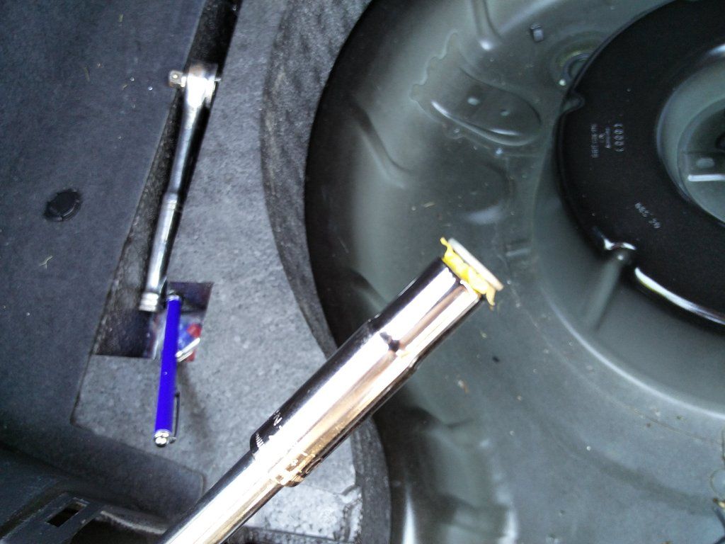
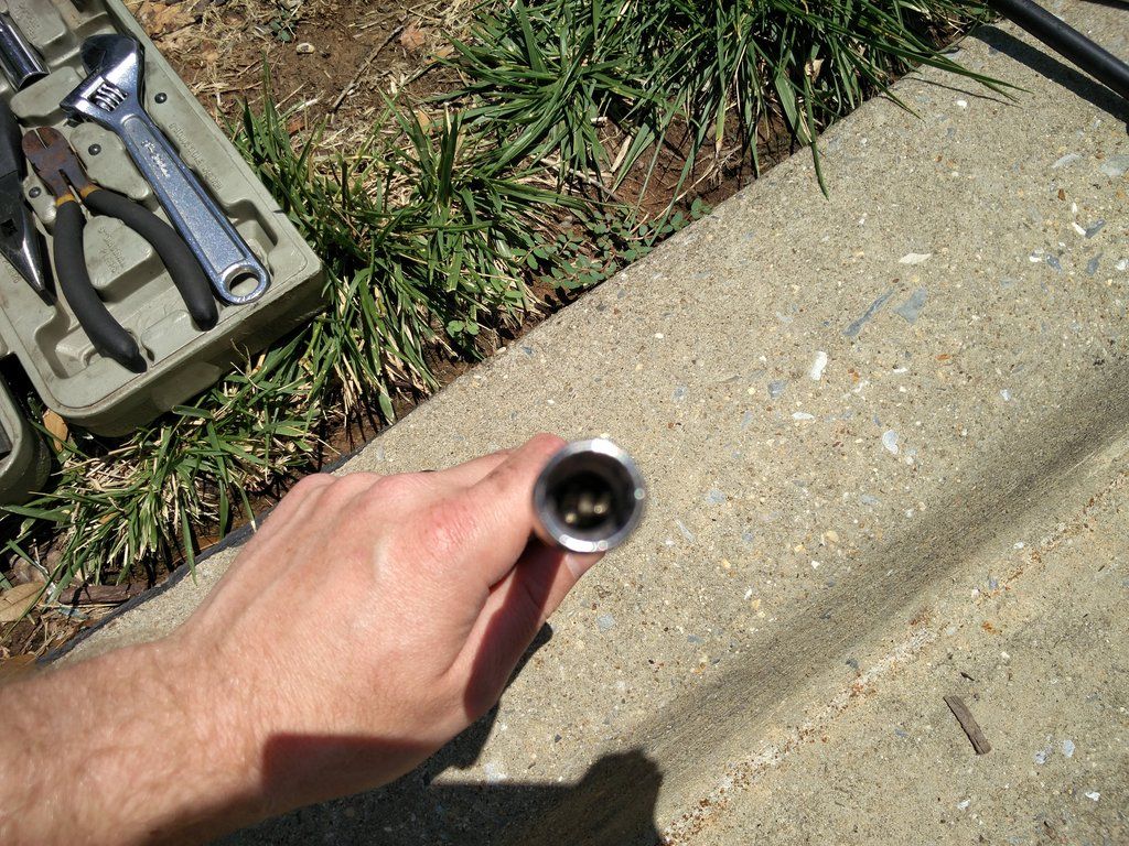
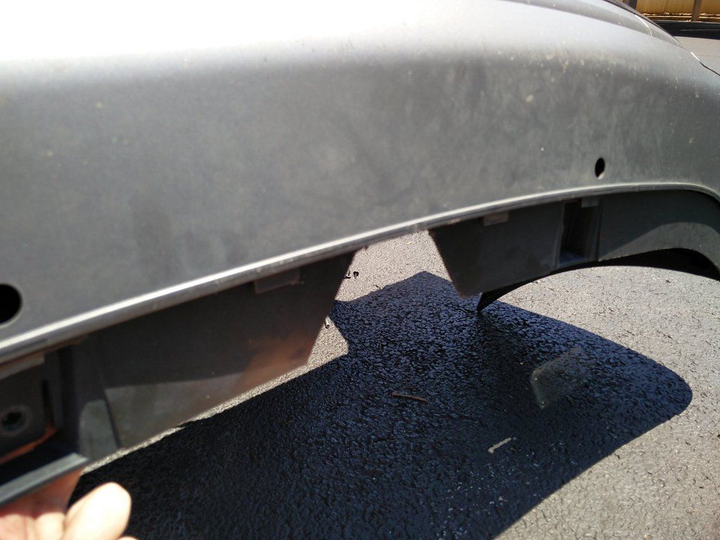
Ok, now the slightly tricky part. There are two 10mm nuts holding the bumper on. Each of these are well inside the body so you need a decent extension and a deep socket. (IMPORTANT: place a small magnet inside the deep socket to avoid dropping the nut down inside the unibody shell!!) Sorry for the photo quality.
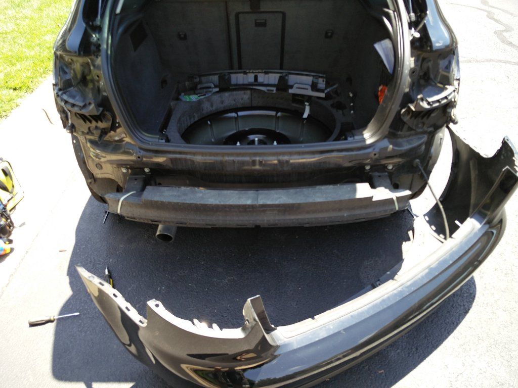
Now you can pop the bumper cover off! Be careful with the backup sensors if you have them.
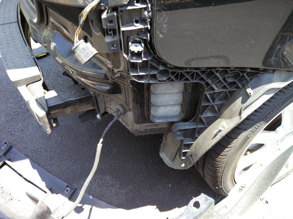
In order to get the hitch into place, I had to remove the bumper frame (six 14mm bolts). You might be able to squeeze it in without removing the frame if you are really good at those puzzles that ask you to get a giant ball out of a tiny hole
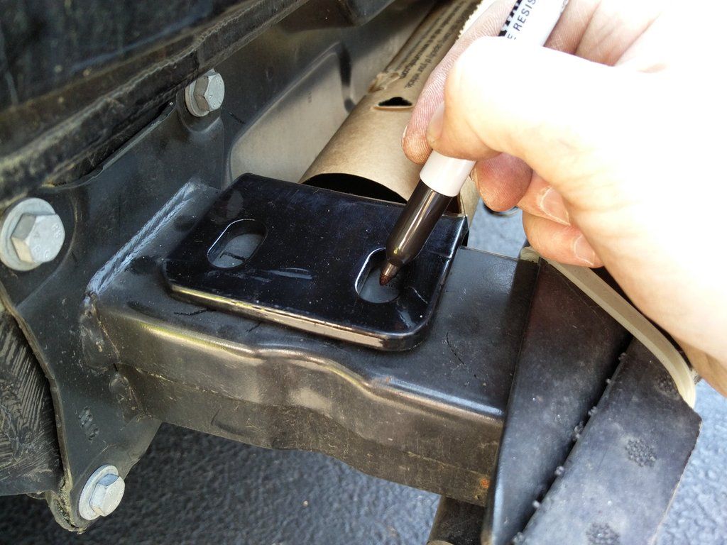
Once in place, mark the four holes for the ends AND the two holes on the spare tire pan. That's where the 3/8" carriage bolts go. Make sure everything is centered and in place before you mark the holes. Also, there are two existing holes on the bumper frame. Ignore these! Don't try to use them.
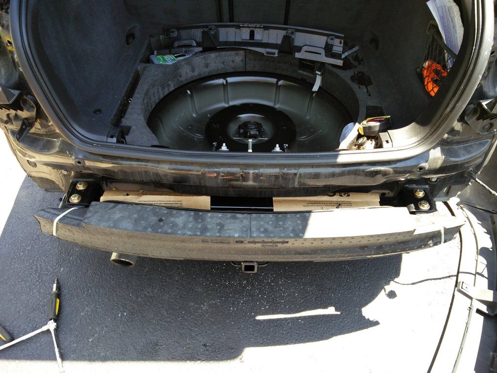
Once marked, remove the bumper frame and drill with 1/2". (I drilled a 1/8" starter first). Also drill a 3/8" hold in two places in the spare tire pan. Then bolt everything together. If it doesn't look like this, you may have done something wrong
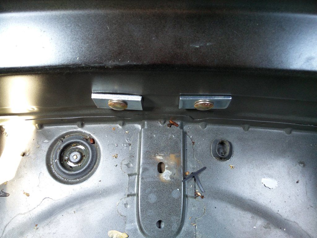
Here are the carriage bolt heads inside the spare tire pan:
Now the fun part! The bumper cover needs to be trimmed slightly. The instructions posted above give you a good template on how to trim. Remember to measure twice - cut once!
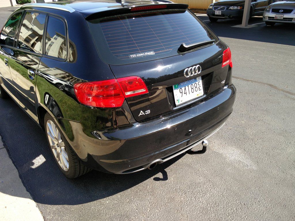
Now reinstall the bumper cover. Installation is the reverse of removal... duh Just work it one step at a time and it should all line up nicely. And the final photos:
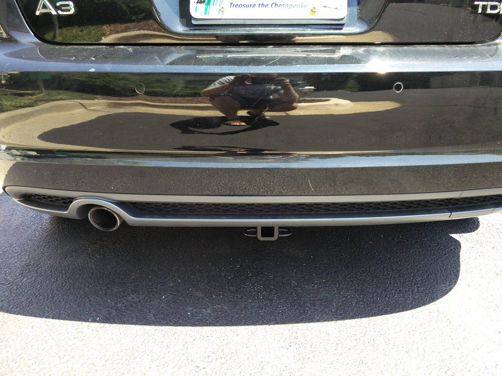
I bought the euro style 2" ball just because it looks a little cleaner. You can use just about any receiver with the right amount of rise.
Trailer lighting conversion kit installation:
This particular vehicle uses a simple "2-wire" system for its rear lights so there are plenty of converters out there that can convert the tail light signals into trailer light signals. The particular converter focused on here is the Curt Manufacturing C56236. More information can be found here:
https://www.etrailer.com/Custom-Fit-Vehicle-Wiring/Curt/C56236.html
And the installation instructions can be found here:
https://www.curtmfg.com/masterlibrary/56236/installsheet/CME_56236_INS.PDF
The instructions are not vehicle specific so are of limited use. Hopefully this guide will aid others in avoiding some of the pitfalls that I fell victim to.
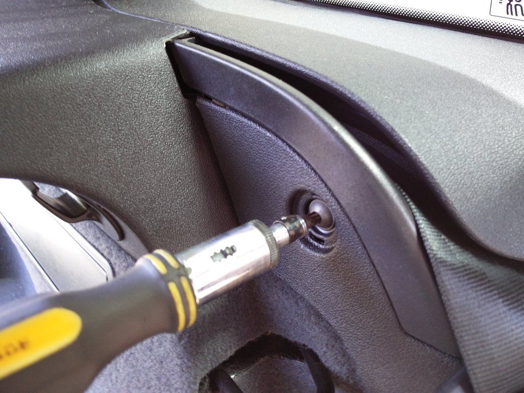
First step is to take everything out of the trunk including under the floor (where the spare tire is kept). Then you need to remove the plastic cover where the catch mechanism is for the hatch. This just pulls straight up with no tools. There are four metal clips underneath that are pretty tough (haven't broken one yet!). To remove the side panels, there are two screws for each. The first is under a little pop out cover behind the rear seat. Fold the seat down and you will see it. Remove this torx screw.
Once you remove the top screw, bend away the plastic cover and you'll see another larger torx screw.
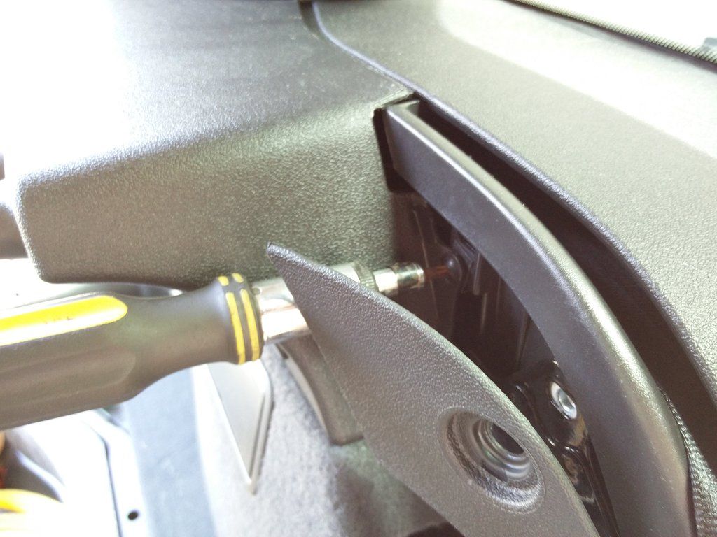
Once this is out, the whole side piece will come out. Just be careful of wires to the light (on the driver side) and wires to the power socket (on the passenger side).
For 12V power, I tapped directly into the wiring for the power socket. I did this by cutting the wire (pull the fuse first!) and soldering all the wires together with plenty of heat shrink tubing.
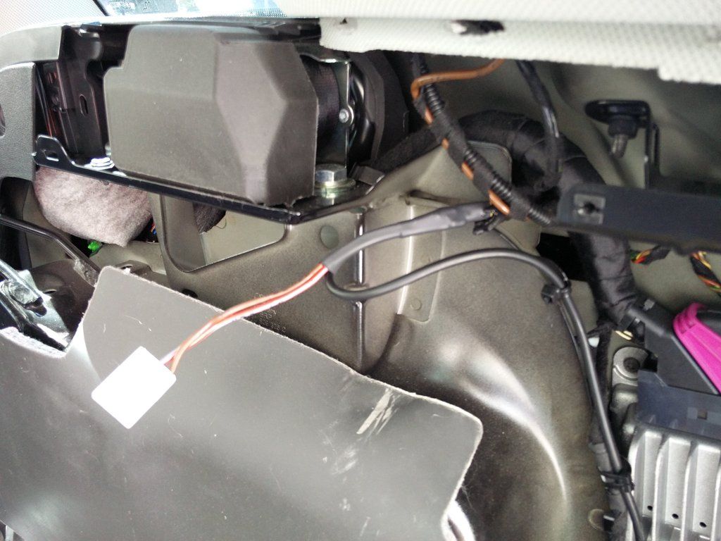
According to the instructions with the kit, you're supposed to run a 12AWG cable from the battery just for this converter. That's far too much work for me and I think it's more than adequate.
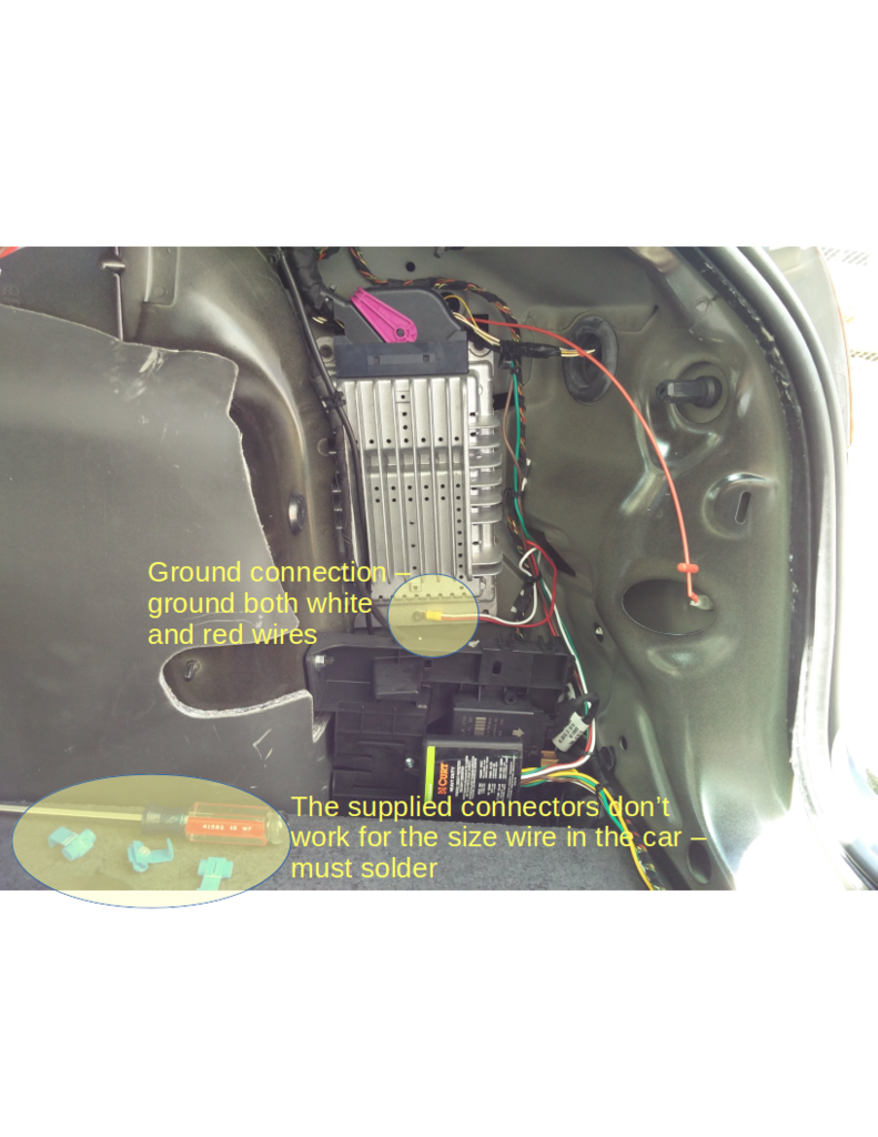
The actual converter is designed to be installed on the driver's side (as evidenced by the wire to the right tail light being quite a bit longer than the other wires), however, I liked it better on the passenger's side because of the 12V power available. So I cut the wire for the right tailight and spliced it into the left taillight signal wire into the converter.
The converter comes with these cheap cut-in connectors that are designed to cut the insulation on the wires for the tailights but not cut the cables. However, the wires are so small in this car that these connectors do not work. You need to strip the tailight wires and solder in or use some other method (perhaps different connectors?). I always prefer soldering.
This car uses a strange arrangement for the taillights. There are LEDs in the enclosure for the taillights and then three single filament incandescent bulbs. The LEDs are only on when the tailights are on - which makes sense. However, the three big bulbs each have their own wire into the enclosure but all three wires always energize at the same time. All three bulbs illuminate for turn, brake, or flasher. Also, one of the bulbs is amber coated but behind a red filter - not sure why.
Anyway, here is a table of the wire colours and their function for the passenger's side:
1 = BRN = Ground
2 = GRY/RED = Brake/Turn
3 = BLK/GRN = Brake/Turn (Amber bulb)
4 = WHT/YEL = Unknown
5 = WHT = Brake/Turn
6 = YEL = LED Tailights
So you need to cut in to the BLK/GRN for the turn/flasher, GRY/RED (or WHT) for the Brake, and YEL for the taillights.
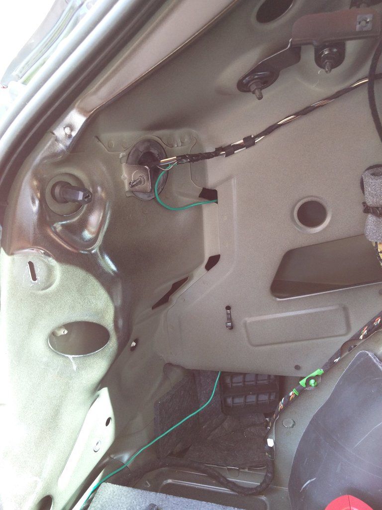
On the driver's side, you need to cut into BLK/WHT for the left turn signal. (Sorry I didn't get the full table for the driver's side).
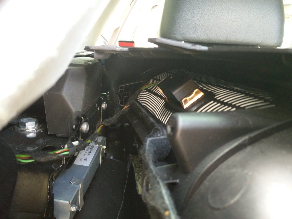
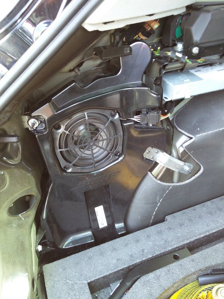
To get to the wiring on the driver's side, you need to remove the woofer assembly.
And attach to the BLK/WHT cable.
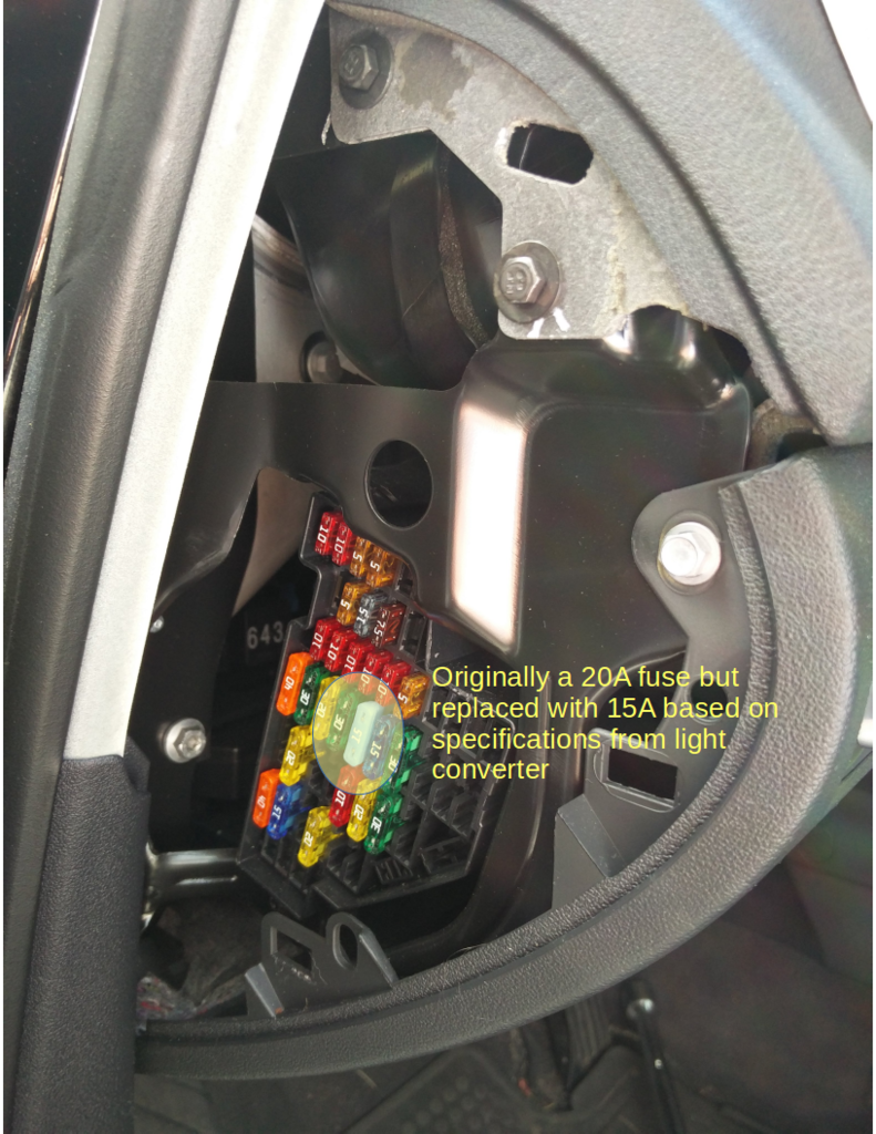
Once that's all done, put the fuse back in and test. Note that I replaced the existing 20A fuse to the power socket with a 15A since that is the recommended protection for the converter.
Assembly is the reverse of removal 
Be sure to test everything by having an assistant hit the brakes, turn signals, and taillights.